Device Model
Device Model
<Circuit Simulation Flow and Device Model>
Current circuit simulation flows according the the following below:
'Circuit Description' → 'Circuit Analysis' → 'Circuit Results Output'
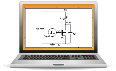
GUI (which stands for Graphical User Interface) software is supplied in a single package that allows for intuitive operation using computer graphics. Previously the [the xxx description] shown to the right of 'Circuit Analysis' below was input using a text editor. Now, the circuit diagram input using the circuit schematic editor is converted in netlist, delivered to the analysis engine, and the simulation automatically executed. Pay attention to the Model Parameter Descriptions below. Also, please note the Device Models in the previous section.
Device Model
A device model is the analytical expression developed based on theoretical and experimental study. Variables and constants that make up this Analytical Expression are model parameters. In other words, device parameters are used to reproduce the actual element characteristics on a simulator.
Circuit Description

Circuit Analysis

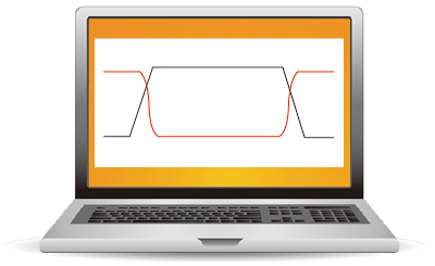
Analysis Results Output
 Input using a Circuit Schematic Editor
| [Resistor Element Description] | R1 | n1 | out1 | 1000 | ||
| [Capacitor Element Description] | C1 | out1 | 0 | 5p | ||
| [MOS Transistor Description] | M1 | out1 | n2 | 0 | 0 | mn1 |
| [Independent Voltage Source Description] | Vpulse | n2 | 0 | pulse (0 3 20n 2n 2n 100n 200n) | ||
| [Transient Analysis Description] | .TRAN | 0.2n | 220n | |||
| [Model Parameter Description] | .model nm1 nmos (level=3 vto=0.65 tox=0.018u nsub=1e15 uo=500 + ucrit=4.5e4 uexp=0.05 tpg=1 ld=0.02u xj=0.05u js=6m pb=0.94 + cj=3.00e-4 cjsw=0.8n cgdo=0.24n cgso=0.20n cgbo=0.021n rd=1 rs=1) |
 Waveform Display
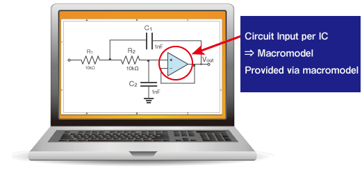
Macromodels
Even though we touched upon it only briefly, hopefully you were able to understand what a SPICE simulator does. Actual electronic circuits typically include multiple ICs and numerous discrete components.
So what is a SPICE model?
The number of elements incorporated into existing ICs can range from several dozen to hundreds of millions in the case of ULSIs. It is not possible to create each element (i.e. transistor) individually and run them on the simulator. The simulation would take too long, making it impractical.
Therefore, SPITherefore, SPICE models for ICs will differ from actual circuits. These models, referred to as macromodels, are obtained by greatly simplifying the circuit.

SPICE models for transSPICE models for transistors, diodes, SiC power devices, LEDs, IGBTs, and ICs (i.e. opamps/ comparators, reset ICs, linear regulators) are available on ROHM's website, found here.